|
|
|
|
|
|
Technical
Info
Key Highlights of SAE JS34 Specification
for Lubricant Fittings |
| This specification is the most important
and common standard for grease fittings. Many of the fittings
we sell meet this standard. These considerations are important
because the cost of a grease fitting is minimal in comparison
to the equipment it is installed on. If a fitting fails, liability
can be substantial. Please consider this information when reviewing
your grease fitting needs. There are many unhardened and poorly
manufactured fittings in the market. You get what you pay for. |
- Material and Manufacture:
SAE JS34 requires that grease fittings be case hardened
0.13 to 0.23 mm deep, with a minimum hardness of 83
Rockwell on the 15N scale.
- Dimensions and Tolerances:
Unless specified, the tolerances on all dimensions are to
be +/- 0.3 mm.
- Check Valves: Fittings should
be equipped with check valves.
- Springs:Although not specified,
the springs used inside the fittings need to be
tempered. One common failure occurs when a spring breaks
or distorts and the ball check then will not retract. Grease
will leak out at the end.
- Pipe Threads: Pipe threads
shall conform with the detail in SAE J476 (copies available).
- Finish: The fittings must
be plated with a suitable material that passes a salt spray
test in accordance with ASTM B 117 (72 hours to red rust).
Efforts must be taken to prevent hydrogen embrittlement
during plating.
|
PTF - SAE short taper pipe thread
NPTF - American National taper pipe thread for Dryseal pressure-tight
joints
NPSM - American National straight pipe thread for mechanical
joints
NPSI - American National straight intermediate pipe thread
BSP - British Standard pipe thread
AS, AS2, AS3 fittings conform to SAE AS35411
ASI fittings conform to Boeing BPS-F-219 |
FITTING
MEASUREMENTS
To help you speed up detailing
and specifying, virtually all fittings are illustrated
with the complete dimensional data indicated... ready
for transfer to your blueprints. |
|
|
 |
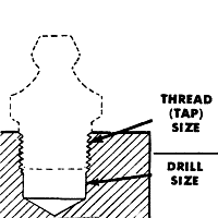
DRILLING
AND TAPPING
For Threaded Fittings
Fitting Thread Size |
Tap Drill Selection for Standard
Thread Fittings |
Drill Size Selection for Spin
Drive Fittings |
1/4" 28 |
#3 (for soft metal use #5) |
"A" - .234"
dia.* |
5/16" -32 |
9/32" (for soft metal
use "J") |
- |
1/8" Pipe |
11/32" (for soft metal
use "R") |
3/8" - .375" dia.* |
1/4" Pipe |
7/16" |
- |
* Drill sizes given
are nominal and may vary with different types of material.
For maximum effectiveness, test applications should
be conducted considering the type of material into which
the fitting is to be installed (steel, brass, aluminum,
etc.). Production tolerances of hole must be taken in
consideration when conducting test. |
HOW
TO DETERMINE
PIPE THREAD SIZES
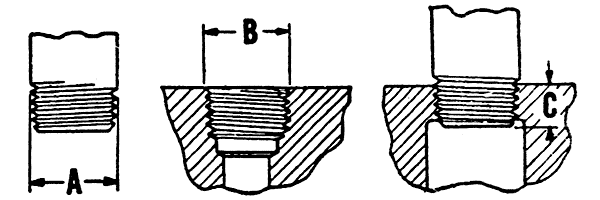
Male Threads
- Measure outside diameter of large portion of thread
at "A"; find figure nearest this dimension
in column I of chart; and directly opposite in column
II is ther nominal pipe (or pipe thread) size.
Female Threads
- Measure outside diameter of thread at "B";
find figure nearest this dimension in column I of chart;
and directly opposite in column II is the nominal pipe
(or pipe thread) size.

|
| I
Outside diameter |
II
Nominal
size
(P.T.)
inch
|
Normal
engagement
for tight joint
(dimen "C")
inch |
Number
of
threads
per
inch |
| Approx.
(fraction)
inch |
Actual
(decimal)
inch |
| 13/32
35/64
43/64
27/32
1-3/64
1-5/16
1-21/32
1-29/32
2-3/8 |
.405
.540
.675
.840
1.050
1.315
1.660
1.900
2.375 |
1/8
1/4
3/8
1/2
3/4
1
1-1/4
1-1/2
2 |
1/4
3/8
3/8
1/2
9/16
11/16
11/16
11/16
3/4 |
27
18
18
14
14
11-1/2
11-1/2
11-1/2
11-1/2 |
|
|
| ACTUAL SIZE OF PIPE
THREAD AT SMALL END |
|
|
|
|
 |
|
 |
|
|
|
|


